

Version 4.0.0 of MicroStrain ROS Driver now available


WHY MICROSTRAIN?
MicroStrain sensors drive innovation across a wide range of applications including mobile robotics and precision agriculture. We offer inertial measurement units (IMUs), vertical reference units (VRUs), attitude and heading reference systems (AHRS), and complete inertial navigation systems (GNSS/INS). With an unmatched dedication to innovation, we're committed to providing solutions that make lives easier today while preparing for tomorrow's challenges.
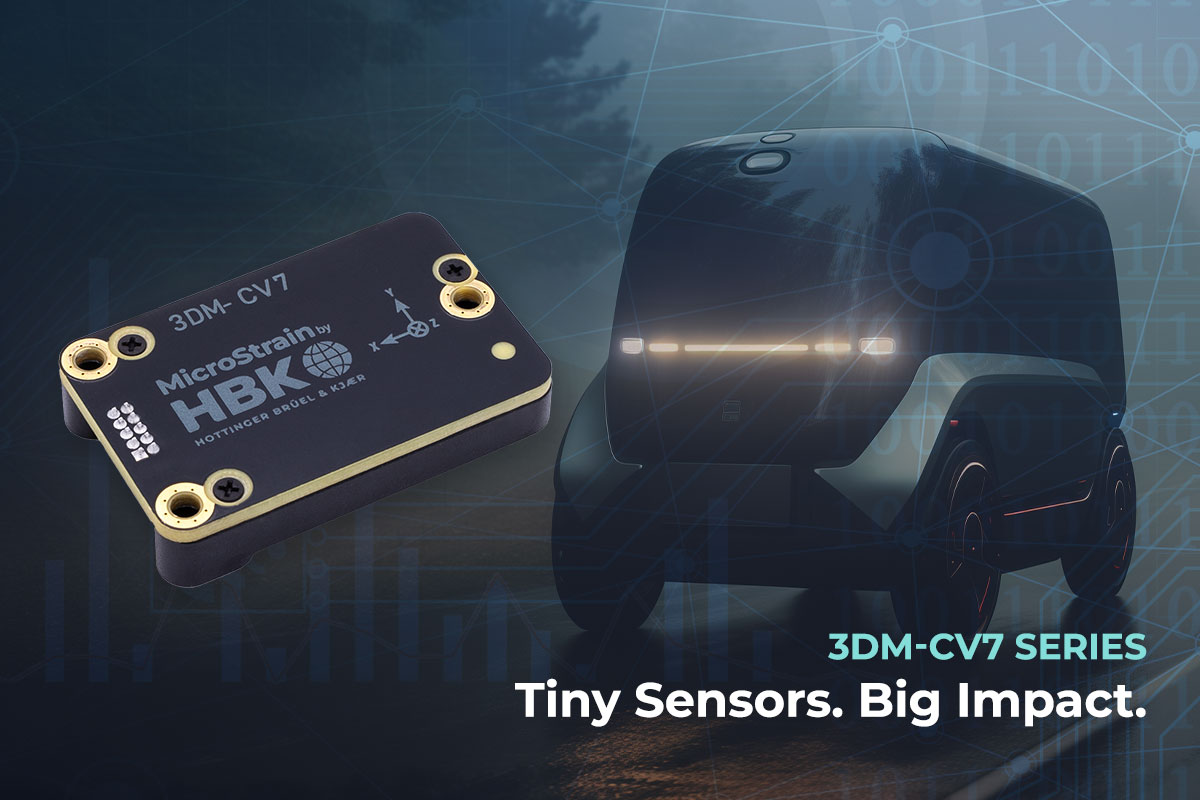
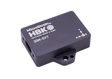
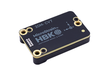
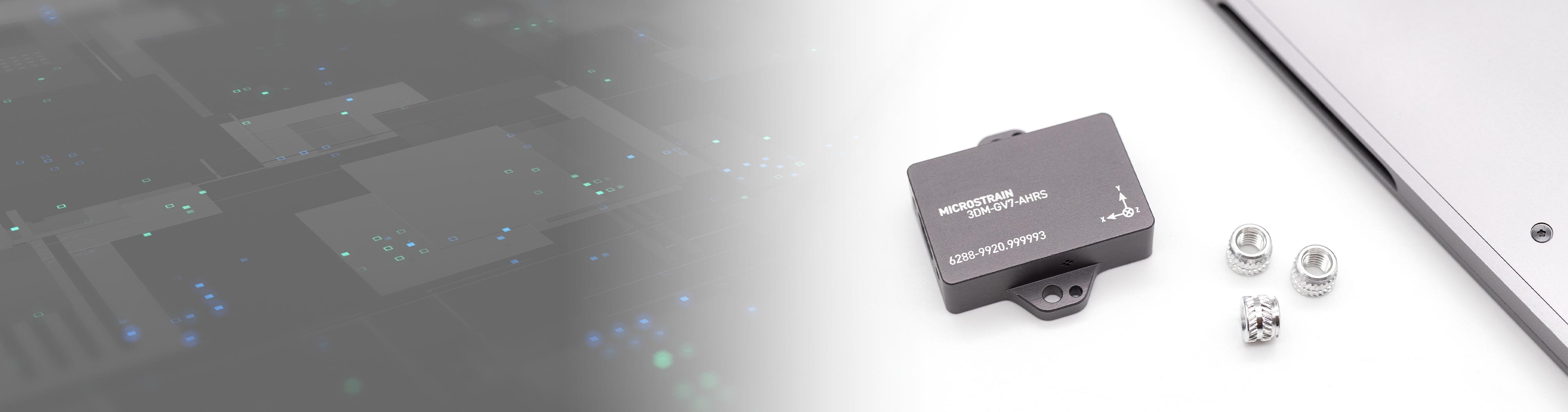
Sensor Spotlight: 3DM-CV7 Series
Tactical grade value-focused embeddable IMU/VRU, IMU/AHRS, and INS. Individually calibrated for optimal performance. Cutting-edge orientation algorithms, advanced time management, and flexible event triggering system make this ideal for mobile robotics applications.
|
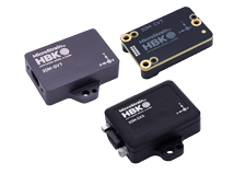
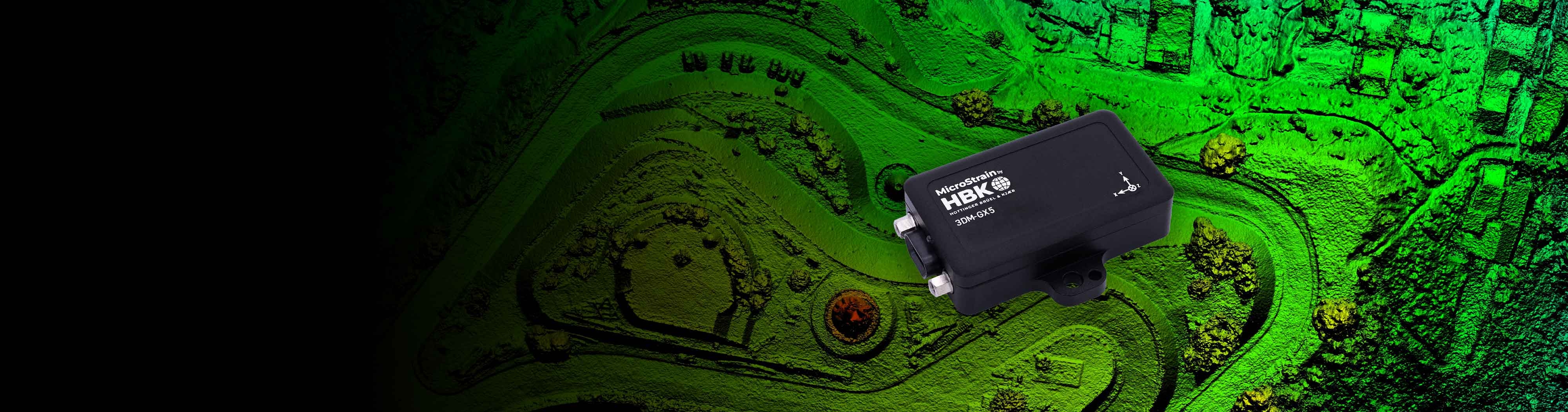
Sensors built to take on your most challenging applications. When it matters, choose MicroStrain.
|
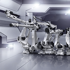
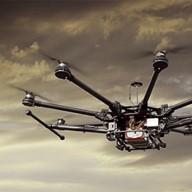
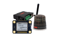
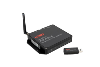
Microstrain’s inertial and wireless sensors detect and monitor vibration and temperature on a manned, unmanned, and autonomous vehicles. For aerial vehicles, our sensors report position, velocity, and attitude. In ground vehicles, our sensors provide localization and mapping. Use Sensor Cloud to capture and organize data. |
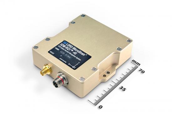
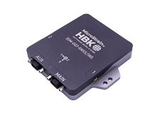
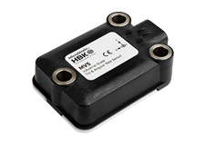
The 3DMGQ7-GNSS/INS is an all-in-one navigation solution featuring centimeter-level position accuracy. A dual-antenna RTK-enabled INS delivers outstanding performance, even in unpredictable conditions. The GQ7 is the best single-vendor RTK navigation solution available to eliminate programming time and enable manufactures to develop new innovations faster than ever before.
|
A prototype eVTOL created by Beta Technologies to deliver human organs for critical transplant operations. MicroStrain sensors were used to accurately capture critical measurements in many environments to ensure successful missions. |
OUR PARTNERS ARE WORLD-CLASS INNOVATORS