

- By
- Posted Wednesday, July 14, 2021 - 11:45
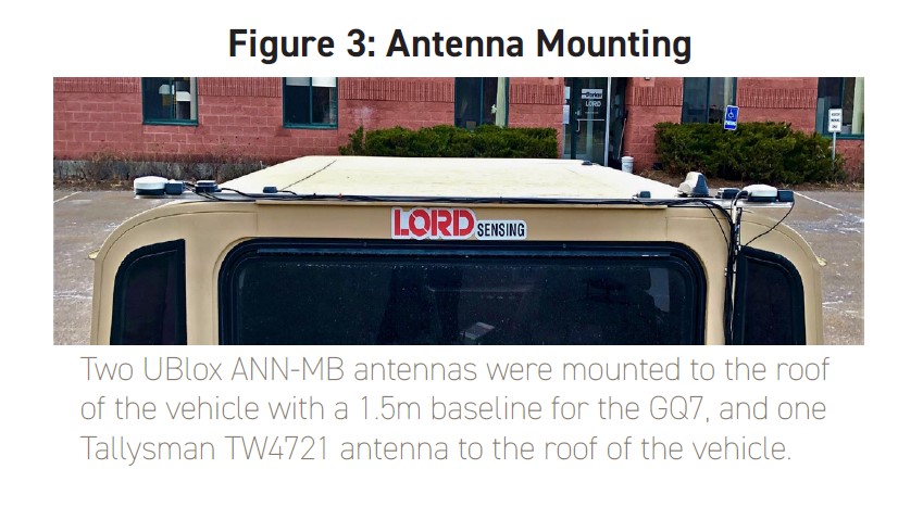
The new 3DMGQ7-GNSS/INS builds on the success of the 3DMGX5-GNSS/INS and adds many features desired by customers which resolve common challenges in specific use cases. This test report highlights four evolutionary improvements.
Read the complete White Paper and Test Comparison Report here.
Background
The new 3DMGX7-GNSS/INS builds on the success of the 3DMGX5-GNSS/INS and adds many features desired by customers which resolve common challenges in specific use cases. This test report highlights four evolutionary improvements:
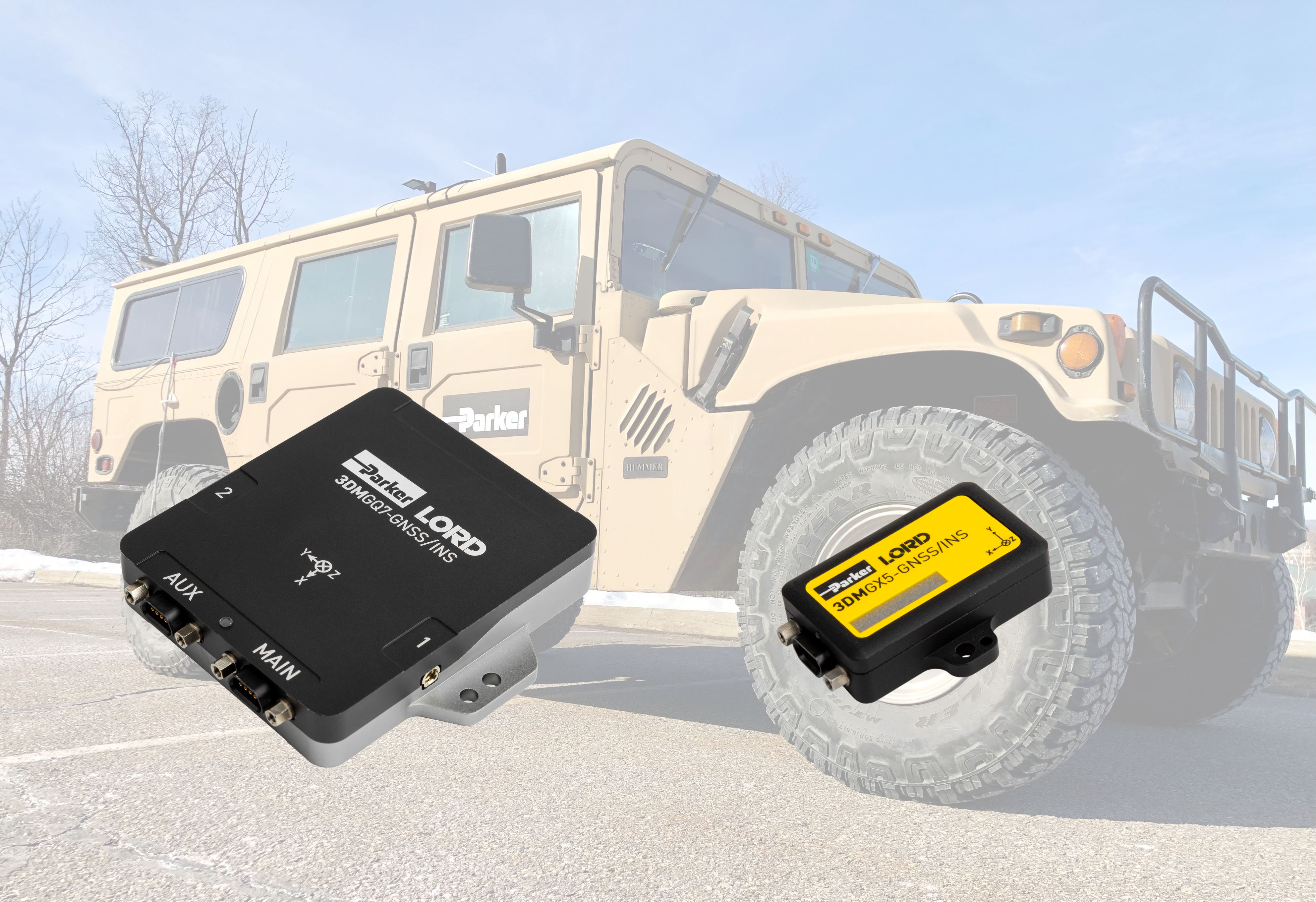
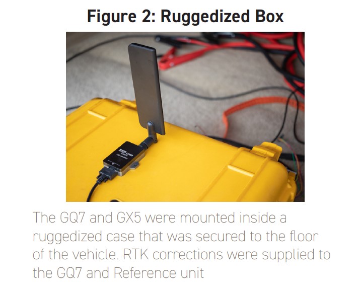
All four tests were completed using a wheeled vehicle with an emphasis on as similar a physical configuration as possible between the two sensors: 3DMGQ7-GNSS/INS (aka GQ7); and 3DMGX5-GNSS/INS (aka GX5 and formerly known as GX5-45). The GQ7 and GX5 were mounted with the same orientation inside a ruggedized case that was mounted to the bed of the vehicle (see Figure 2). The GQ7’s GNSS dual-antennas and the GX5‘s single GNSS antenna were mounted to the roof (see Figure 3) in proximal locations. For each test, the sensors settings were configured appropriately for a wheeled vehicle application.
A higher grade inertial sensor, herin referred to as “Reference”, was used as the truth reference for error calculation in comparison of the GQ7 and GX5. The Reference was also mounted in the ruggedized case and RTCM corrections were simultaneously supplied to the GQ7 and the Reference from the same cellular modem during testing.
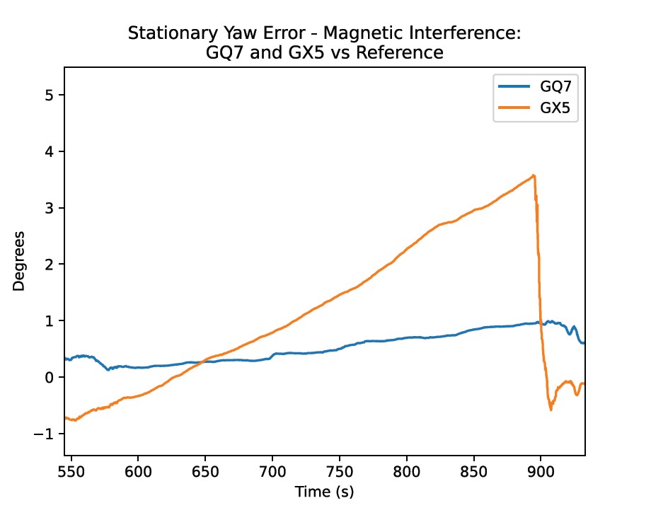
Test 1: Dual-Antenna Stationary Heading
Motivation:
When it is not possible to use a magnetometer due to Magnetic Interference (MI), single antenna GNSS/INS navigation sensors are unable to obtain precise and accurate heading during periods of low linear acceleration. The GQ7 solves this challenge by adding dual-antenna heading aiding. In a system like the GX5, heading will drift over time during these stationary periods, while the GQ7 will maintain a stable heading.
Target Applications:
Sensor Configuration:
Heading Initialization and Aiding Sources:GQ7: Dual-Antenna GNSS and GNSS Kinematic Heading Initialization, GNSS Postiion and Velocity Aiding, GNSS Heading Aiding
GX5: (single antenna) GNSS Velocity Vector GNSS Heading Aiding
Procedure:
Drive for 5 minute. Come to a stop. Remain stationary for 5 minute drift eriod. Drive for 1 minute to hightlight effect of yaw on positional accuracy.
Results:
For this test case, the GQ7 had bounded error of 0.88° and the GX5 drifted at a rate of 0.87° per minute during the 5 minute stationary period.
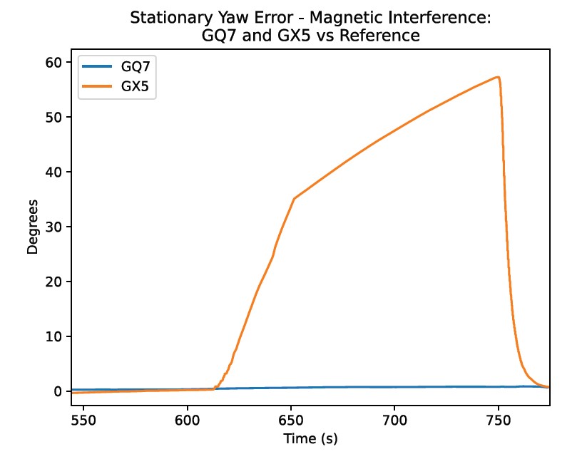
Test 2: Magnetic Interference Immunity
Motivation:
The GQ7 solves common challenges with magnetometers. Magnetometers can provide an accurate heading estimate based on Earth’s magnetic field if there is little to no magnetic interference (MI). If there is MI from large proximal moving ferromagnetic components like nearby vehicles, trains, and gear boxes, magnetometers can prove to be challenging to impossible to calibrate and employ as a heading aiding source. The GQ7’s dual-antennas are not susceptible to MI and therefore can provide accurate heading in these situations - a feat previously impossible in single-antenna systems.
Target Applications:
Sensor Configuration:
Heading Initialization and Aiding Sources:GQ7: Dual-Antenna GNSS and GNSS Kinematic Heading Initialization, GNSS position and Velocity Aiding, GNSS Heading Aiding
GX5: Magnetometer, Single-Antenna GNSS Velocity Vector, GNSS Heading Aiding.
(Note: For this test, adaptive magnetometer measurements were turned off. When enabled, they significantly reduce heading drift due to magnetic interference for transient MI, but do not eliminate it entirely especially for continuous MI. This configuration illustrates the real effect of external MI for devices that do not implement similar algorithms for transient MI.)
Procedure:
Drive for 8:30, park for 1 minute, maintain constant MI near the GQ7 and GX5 for 45 seconds, remain parked for 2 minutes, drive for 45 seconds.
Results:
The GQ7’s dual-antenna heading is immune to MI and maintains accurate heading during MI while the GX5 heading drifts an unacceptable amount.
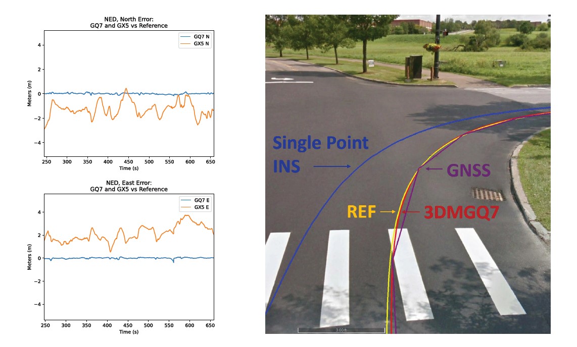
Test 3: Dual Antenna + RTK vs Single-antenna
Motivation:
The GQ7, when paired with the 3DMRTK and SensorCloudRTK, increases positional accuracyby 100x by providing 1cm + 1ppm positional accuracy in most major urban areas and coverage is always expanding.
Target Applications:
Sensor Configuration:
Heading Initialization and Aiding Sources:GQ7: Dual-Antenna GNSS and GNSS Kinematic Heading Initialization, GNSS position and Velocity Aiding, GNSS Heading Aiding, configure comms with 3DMRTK
GX5: Single-Antenna GNSS Velocity Vector, GNSS Heading Aiding.
Drive for 5 minutes. Drive through intersection with sidewalk adjacent to road.
Results:
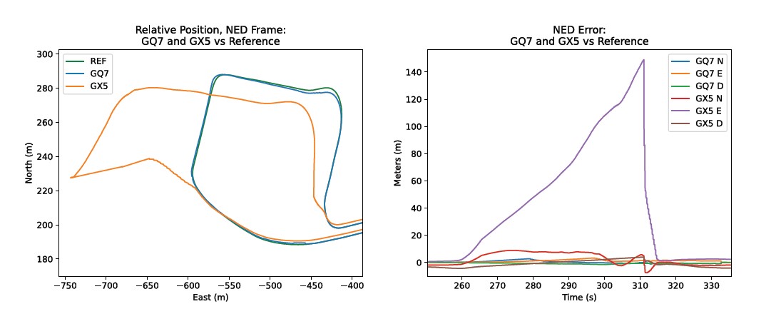
Test 4: Effects of Wheel Odometry on GNSS Signal Attenuation Positional Error
Motivation:
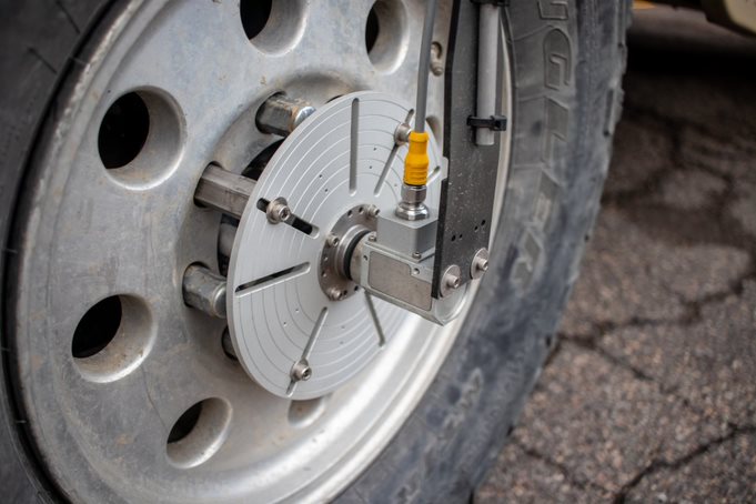 An auxilliary port was added to the GQ7 to provide external inputs to the GQ7’s Kalman Filter. One of these inputs is wheel odometry (for wheeled vehicles). The GQ7 Navigation Filter supports external speed measurements, either through a hardware encoder interface or digital message input. Odometry aiding can greatly increase navigation performance during GNSS outage scenarios. A Michigan Scientific High Resolution Wheel Pulse Transducer E512 was used for odometer aiding in this test as seen in the image at right.
Target Applications:
Sensor Configuration:
Heading Initialization and Aiding Sources:GQ7: Wheel Odometry, Dual-Antenna GNSS and GNSS Kinematic Heading Initialization, Zero Velocity Control, GNSS position and Velocity Aiding, GNSS Heading Aiding, configure comms with 3DMRTK dongle
GX5: Single-Antenna GNSS Velocity Vector, Zeri Velocity Control, GNSS Heading Aiding.
Procedure
Drive for 5 minutes. Attenuate GNSS signals of GQ7 and GX5 while driving. Maintain attenuation for 1 minute through curvy section of road while driving.
Results:
During attenuation, the GQ7 stays nearly superimposed on the reference position thanks to its higher quality IMU and odometry input, while the GX5 drifts 140 meters.