


MicroStrain™ Knowledge Base
Select a product family


General Documentation
Technical Notes
- LVDT Mounting Basics
- Displacement Temperature Coefficient
- LVDT vs. LVDT Comparison
- Using a Multimeter with the DEMOD-DC®
- LVDT-Link-LXRS® Understanding the Calibration
- Field Calibration of the Gauging LVDT
- Using the DEMOD-DC® with V-Link®-LXRS™ and SG-Link®-LXRS™
- 6103-0000 MG- LVDT-3
- 6103-0100 MG- LVDT-6
- 6103-0200 MG- LVDT-9
- MG-DVRT-X
- MG-TBODY-X with MG-DVRT-X
- LEMO Connector Assembly pdf 6129-0000 CBL1
- LEMO Connector Wiring Diagram
- MG- LVDT Ball Tip
Software/Firmware
There were no results
LORD Displacement sensors are offered in smooth and threaded shell versions. Depending on the application, one of these types may make more sense than the other.
Off the shelf, sensors will come with a smooth stainless steel body. For non-gauging contact-type sensors this shell is a 300 series stainless. For gauging contact-types this shell is 400 series.
A smooth shell sensor can be mounted in a fixture or product in a number of ways:
Epoxy the sensor in a close-tolerance through hole
| Pros | Cons |
|---|---|
| Fast integration of the sensor | Core is peramently fixed |
| Provides rigid mounting | Future recalibration difficult or impossible |
| Potential thermal expansion effects |
Use a 3rd party collar clamp to fix the sensor to a product
| Pros | Cons |
|---|---|
| Available in stainless steel and other materials | Requires a means of attaching the collar clamp to the product (Epoxy/fasteners) |
| Offered in a wide range of sizes | Precise sensor alignment is more difficult |
| Sensor is removable |
Through hole with a set screw
| Pros | Cons |
|---|---|
| Fast integration of the sensor | Requires a tapped hole intersecting the sensor hole |
| Stiff mounting, yet removable | Overtightening set screw could damage sensor |
| Resilient to thermal expansion |
Feedthrough/Grommet
| Pros | Cons |
|---|---|
| Sensor is removable | Polymer seals can compromise precise measurements if too soft |
| Grommets can seal around the smooth shell | Threading/accommodation of a grommet |
| Fast integration |
Threaded Shells
Threaded shells are perhaps the easiest to install. They require a tapped hole of the mating thread (shells are offered in both Metric and imperial), and either a follower nut or a set screw to fix the sensor into position. The threaded body allows for precise axial positioning of the sensor, the ability to remove the sensor in the future, and an increased magnetic shielding from the surroundings.
Mounting Rules of Thumb
Avoid Magnetic Influences
All LORD LVDT Sensors are susceptible to outside magnet fields (both static or dynamic). Non-gauging type sensors with smooth shells are the most susceptible due to the thin walls of the 300 series shell. Gauging type sensors, NC-LVDTS, and threaded shell versions of all models have higher resistance to external fields, but it is still recommended that sensors not be exposed to any magnetic fields during use. External fields will influence the output of the sensor and result in incorrect readings. If magnet fields are unavoidable, contact a LORD support engineer to discuss options for custom calibrations or magnetic shielding.
Appropriate Fixture Materials
As a general rule, fixturing should be non-magnetic for all sensors. For NC-LVDTs there is an additional requirement is that the fixture is non-conductive (the target of the NC-LVDT should, however, be conductive!). Depending on the sensor type, and performance customizations (high-res, low noise, low drift, etc.) Magnetic materials, and even "mostly" non-magnetic materials, can have an effect on sensor output. In cases where sensors are mounted in non-ideal materials, LORD can calibrate the sensor in your fixturing to remove any offset or gain errors the fixture is contributing, bringing the sensor back into peak performance.
Sensors with threaded shells, LS-LVDTs, and gauging-type sensors have higher resistance to nearby magnetic materials than the free-sliding smooth body sensors (M-, and S-LVDTs).
Examples of acceptable fixturing materials for Contact-type sensors:
- All polymers/plastics
- Carbon Fiber/composites
- Aluminum
- Non-magnetic stainless steel (300 series)
- Wood
- Ceramic
- Titanium
- Other non-magnetic metals
Examples of influential materials:
- 400-series stainless
- Ferrite
- Iron
- Carbon Steels
Non-contact LVDTS must be mounted in a non-conductive material, such as those listed below. In special cases NC-LVDTs can be mounted in conductive fixturing, but LORD must perform the calibration with the sensor installed in the fixturing. The calibration repeatability is also contingent on careful axial alignment of the sensor within the fixture.
Acceptable Non-contact LVDT fixture materials:
- All Polymers
- Carbon Fiber (limited information)
- Composits
- Wood
- Ceramic
As always, LORD support engineers are available to go over your particular application and work with you to find the optimal way to mount our sensors.
Plan for cable strain relief
Plan to have some room at the back of the sensor for routing the cable out and away to the signal conditioner. The cable we use in our sensor is armored, but is not unbreakable. Pulling on the cable at a sharp angle against the back of the sensor is likely to cause a cable failure, either at the epoxy edge or internal to the sensor. Use your thumb- if the cable turns tighter than the diameter of you thumb, it may be too tight.
Avoid twisting the sensor independent of the cable
It sounds easy to avoid, but we have seen it many times. When installing a threaded body sensor, be sure that the cable is spinning with the sensor! If the cable it plugged into the signal conditioner, or not freely rotating as the sensor is inserted it will eventually over-twist and snap.
As an example. here is the Quick Start Guide for the M-DVRT-9: http://files.microstrain.com/Micro_Sub_DVRT_Quick_Start_Guide.pdf
Page 7 refers to the Slope and Offset that you will need to enter into the Smart Motherboard software.
In the Smart Motherboard software, click Tools.
Click Configuration and the Configuration screen appears.
Select the appropriate channel (remember that each channel, i.e., each DVRT and DEMOD –DVRT signal conditioner card in the Smart Motherboard is calibrated separately) by checking the Channel check box.
Select the Linear Radio Button.
Enter the Slope and Offset in the number scroll boxes.
Select None in the Peak Detect drop-down.
Change the Units from Volts to mm (for millimeters) by wiping through with your mouse.
Click File.
Click Save As Default.
Click File.
Click Return and you are ready to sample in millimeters.
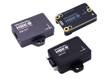
The MG-DVRT Microminiature Gauging and SG-DVRT Subminiature Gauging Differential Variable Reluctance Transducers are typically calibrated with their signal conditioning electronics at the factory. These calibrations are highly accurate and are always recommended. However, under certain conditions the user may determine that a field calibration should be performed. This technical note provides a step-by-step instruction to field calibration and assumes the user is familiar with the DVRT displacement transducer and its signal conditioning electronics (Motherboard, Smart Motherboard, or DEMOD-DC).
No, carbon fiber has not been shown to pose a problem.
Yes, as a courtesy, LORD MicroStrain® will provide an appropriate drill bit and tap to match the DVRT's thread size at a nominal charge.
In most cases, MicroStrain calibrates every DVRT with its accompanying electronics and provides a detailed calibration certificate. The certificate provides 3 methods of calibration and all the particulars including formulas to resolve voltage into engineering units.
- Standard Least Squares Linear Fit provides a simple mathematical method to convert sensor output to displacement and delivers reasonable accuracy.
- Polynomial Fit provides a more mathematically intensive method to convert sensor output to displacement and in turn delivers a high degree of accuracy. A possible drawback to some users of this method may be that it can not accurately report measurements beyond its stroke length (i.e., over-stroking).
- Multi-Segment Linear Fit provides the most mathematically intensive method to convert sensor output to displacement, delivers a high degree of accuracy and is not subject to the drawback of over-stroking.
- Body length to stroke ratios for DVRTs are typically 2.5 to 1 as compared to 6 to 1 for LVDTs.
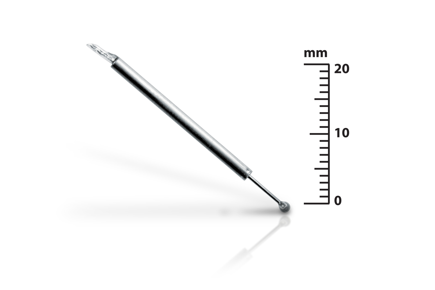
- Microminiature DVRTs are available in body diameters of only 1.5 mm (.060") and with core diameters of only 0.5 mm (.020"); this makes them the World's smallest commercially available linear displacement transducers.
- DVRTs maintain their temperature stability due to the use of two coils arranged differentially.
- Each DVRT is capable of submersion as a standard feature.
- Each DVRT can be hermetically sealed as an option.
- Microminiature DVRTs are available with super-elastic, nickel titanium cores.
- DVRTs have a standard operating temperature range up to 175 degrees C; LVDTs typically only operate up to 85 degrees C.
- DVRTs have been operated successfully in liquid nitrogen; LVDTs typically only operate to -20 degrees C.
The output is an analog DC voltage proportional to linear displacement. The full scale voltage is optionally +/-5 volts or 0-10 volts. The analog voltage is easily read using a multi-meter or DAQ. The voltage can also be read in the digital domain by using LORD MicroStrain® Smart Motherboards. These Smart Motherboards provide a data gateway to PC-based software or to user-programmable LCD displays on the motherboard itself.
Yes. DVRTs can be used in wet environments. One of our customers uses the DVRT to measure mussel growth on the ocean floor. An automotive customer uses the DVRT in a hot oil environment for under-the-hood testing. Our orthopaedic customers use the DVRT for soft and hard tissue testing (in vivo and ex vivo) in cadaver and animal studies.
The spring force on standard units is 0.2 newtons/mm or 1 pound/inch.
Yes. A comparison chart may be found at: http://files.microstrain.com/Displacement-Sensors-Comparison.pdf
Sandard DVRTs can operate up to 100 PSI. However, custom-designed sensors have been used in applications up to 10,000 PSI. Please contact your sales or support engineer for more info.
Typically, every DVRT is calibrated at the factory with its accompanying DEMOD signal conditioner. The calibration is made over the entire system (DVRT and DEMOD) to insure the highest accuracy. DVRTs and DEMODS are color-coded to insure that they stay together as a pair when in use.
LORD MicroStrain® posts links to a number of published scientific papers at: http://www.microstrain.com/company/scientific-papers
The term ‘Motherboard’ refers to the LORD MicroStrain® DEMOD-DVRT or DEMOD-DVRT-TC signal conditioner mounting chassis. The standard Motherboard provides a mounting slot and power to the individual DEMODs. The Smart Motherboard provides a mounting slot, power and digital communications (RS-232) to the individual DEMODs. Both Motherboard and Smart Motherboard provide analog ouput to a DAQ. In addition, Smart Motherboard provides digital output to a computer. Motherboards and Smart motherboards can accommodate 1 to 8 DEMOD cards.
| DVRT Type | Threaded Core | Threaded Body | Core Clamps | Body Clamps | SM-Block Core/Body | Magnetic Mount Core/Body |
|---|---|---|---|---|---|---|
| Subminiature | X | X | X | X | ||
| Subminiature Gauging | X | X | ||||
| Microminiature | X | X | X | X | ||
| Microminiature Gauging | X | X | X | |||
| Non-Contact | X** |
** Non-Contact comes standard with threaded body except for 5.0.