


MicroStrain™ Knowledge Base
Select a product family


There were no results
What is Multipath?
Multipath is the phenomenon whereby a radio signal arrives at a receiver’s antenna by more than one path. This occurs by the reflection, diffraction, or scattering of radio waves from atmospheric ducting, reflection from water bodies or terrestrial objects (like mountains), etc.
Does Multipath impact signal strength?
Yes, multipath propagation of radio signals causes fading of the transmitted signal, which can be indicated by fluctuations in signal strength when received by the signal receiver.
How do I mitigate Multipath?
Pe-position base station or node to mitigate possible multipath interference.
Ensure a clear path to the antenna for the strongest signal, enhancing the strength of the strongest signal AND reducing the strength of the weaker signals.
Learn More: Mutipath Propagation
The Low Battery Indicator is a diagnostic channel that indicates the battery level of the node. It is represented by 3 possible values: 0, 1, and 2.
The “0” value indicates that the battery level is good.
The “1” value indicates that the battery level is low. At this level it is recommended that the batteries be replaced. This indicates that critical battery level is imminent. Please replace batteries when this warning indicator is thrown. Once critical battery level indicator is reached the node will stop sampling.
The “2” value indicates that the battery level is critically low. At this level the node will stop sampling.
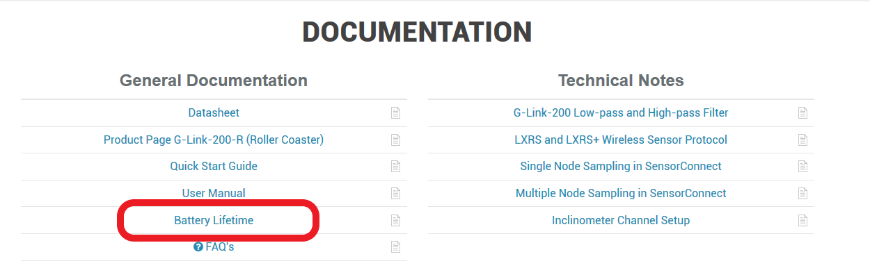
The expected battery lifetime depends on a combination of variables, such as the sampling mode, sample rate, RF transmit power, number of active channels, etc. To determine the expected battery life of your node please use the Battery Lifetime link provided on the specific node’s product page on our website.
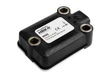
The IEPE-Link™ -LXRS® accepts inputs from most IEPE sensors using the industry standard 10-32 mini-coaxial connector and 2.3 mA constant current excitation.
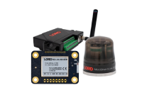
The WSDA-RGD (with internal GX3 inertial sensor) is configured to produce the following messages on startup.
GPS Data (1 Hz):
- UTC Time
- LLH Position
- NED Velocity
AHRS Data (100 Hz):
- Euler Angles
From this output the WSDA logs:
GPS (1 Hz):
- latitude
- longitude
- height above ellipsoid
- height above MSL
- horizontal accuracy
- vertical accuracy
- speed
AHRS (100 Hz):
- roll
- pitch
- yaw
The WSDA-RGD does not log any data until it gets a valid time, if it is set to get time from GPS only it will not log any output from the GX3 until the UTC timestamp from the GX3 is valid, even though the GX3 is producing valid AHRS data.
This data is not user configurable and is not available as a live stream through LiveConnect.
All LORD MicroStrain wireless sensor nodes, wireless base stations, and wireless sensor data aggregators are shipped from the factory with their radio frequency set to channel 15 (2.425 GHz).
This channel setting was established during 2012.
Previously all wireless products were set to channel 25 (2.475 GHz).
If you are mixing new nodes and base stations with older nodes and base stations, please be cognizant of these different channel settings.
The Node Discovery function of Node Commander will help you sort out which nodes are on what channels; Node Discovery is channel independent and allows the base station to communicate with any node, no matter what channel it is on
Sampling methods such as synchronized sampling, low duty cycle, network broadcast, etc. require that all nodes are on the same frequency so you will want to insure that you have adjusted the channels settings of the nodes to suit.
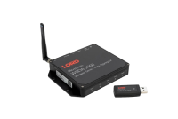
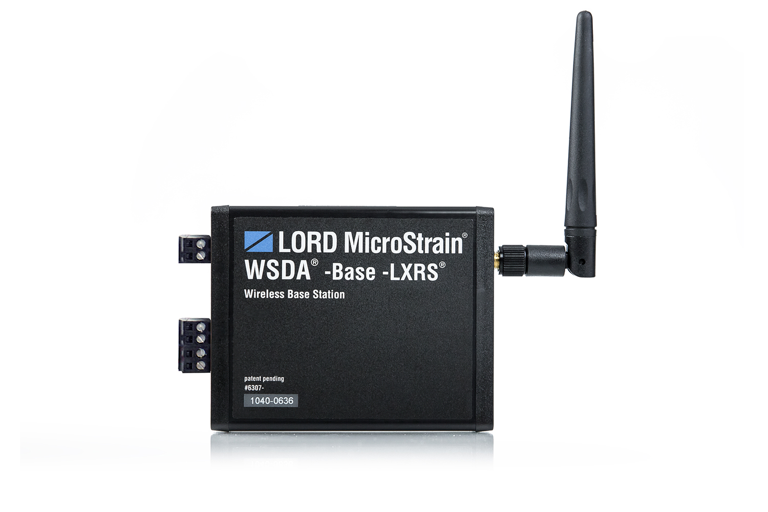
The LORD MicroStrain® WSDA-Base-101-LXRS Wireless Analog Output Base Station supports all data acquisition sessions between wireless nodes and host computers including Synchronized Sampling (both Continuous and Burst modes), Armed Datalogging, Datalogging, Streaming and Low Duty Cycle. As an integral feature, the WSDA-Base-101-LXRS has an analog output back panel that supports analog data acquisition equipment (DAQs). Up to 8 sensor channels from one or multiple wireless nodes can be fed into a DAQ with simultaneous digital feed into a PC, or into a DAQ with the PC removed (stand-alone configuration). Each channel on the back panel has a 0 to 3 volt range representing the particular sensor’s full scale output. In some environments and with some equipment, the 0 to 3 volt range is not appropriate; many types of programmable logic controllers (PLCs) and DAQs have only current loop inputs, are therefore incompatible with voltage output sensors, and require a 4 to 20 mA output range to operate. This technical note demonstrates how to convert the 0 to 3 volt output to a 4 to 20 mA output using a third party converter and assumes familiarity with the WSDA-Base-101-LXRS, LORD MicroStrain wireless nodes and Node Commander software.
Microsoft Excel displays the timestamp contained in the wireless node data files incorrectly. If you were to open the CSV file with Microsoft Notepad, you will see that the timestamp is shown properly. In order to get Excel to show the human readable time, follow the below procedure:
- Highlight all of column A (column with the timestamp)
- Right click on highlighted region and select Format cells...
- Select the Number Tab in the window that open and choose Custom from the Category box
- Scroll to the bottom of the list in the Type box, find this entry: m/d/yyyy h:mm and click it
- Add to the entry an :ss.000 so it now looks like this: m/d/yyyy h:mm:ss.000
- Click OK
The timestamp will now be correct.
In FINITE sampling, the user sets a total number of samples to be taken which equates to a time period. Because the sampling rate per second is known, the user can adjust the number of samples to be taken to determine how long the sampling period will be.
In CONTINUOUS sampling, the user does not set the total number of samples and therefore does not set the time of the sampling period. By selecting CONTINUOUS sampling, the user is instructing the system to sample data until the user manually stops the sampling (via software), the power is cycled, the on-board datalogging memory is full, the battery dies, the power fails, etc.
LORD MicroStrain® Wireless Sensor Networks provide several data acquisition modes including:
- Synchronized Sampling
- Armed Datalogging
- Streaming
- Duty Cycle
See the particular wireless node for specifics.