

NEW VERSION
There is a new version of this product available. The product on this page has been discontinued and the datasheet and manual are provided for informational purposes.
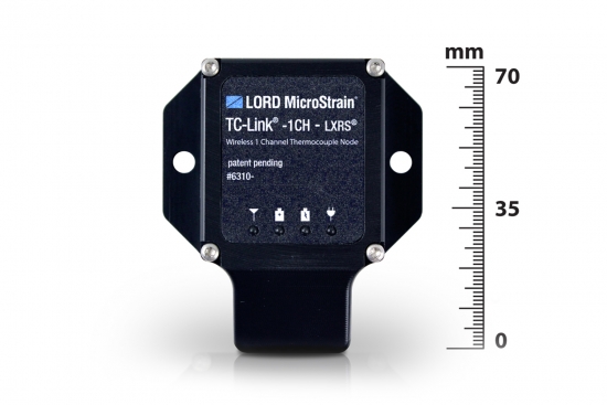
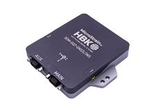
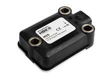
The TC-Link® -1CH -LXRS® is a miniature, specialized wireless sensor node designed for data acquisition from standard thermocouples.
Product Highlights
Datasheet Software
Wireless Simplicity, Hardwired Reliability
High Performance
Ease of Use
Cost Effective
|
General |
|
|---|---|
|
Sensor input channels |
Thermocouple input, 1 channel |
|
Integrated sensors |
Temperature CJC, 1 channel |
|
Data storage capacity |
2 Megabytes (up to 500,000 data points) |
|
Thermocouple Input |
|
|
Measurement range |
-210 °C to 1820 °C (depending on the thermocouple type) |
|
Accuracy |
± 0.1 % of full scale or ± 2 °C, whichever is greater (does not include error from sensor or wire) |
|
Resolution |
0.0625 °C, 24 bit |
|
Repeatability |
± 0.1 °C (does not include error from sensor or wire) |
|
Integrated Temperature Cold Junction Compensation (CJC) Channel |
|
|
Compensation range |
-40 °C to 85 °C |
|
Accuracy |
± 0.5 °C (from 0 to 70 °C) |
|
Resolution |
12 bit |
|
Sampling |
|
|
Sampling modes |
Synchronized, low duty cycle, datalogging |
|
Sampling rates |
Continuous sampling: 1 sample/hour to 64 Hz Datalogging: 1 sample/hour to 64 Hz |
|
Sample rate stability |
± 3 ppm |
|
Network capacity |
Up to 2000 nodes per RF channel (and per gateway) depending on the number of active channels and sampling settings. Refer to the system bandwidth calculator: http://www.microstrain.com/configure-your-system |
|
Synchronization between nodes |
± 32 μsec |
|
Operating Parameters |
|
|
Radio frequency (RF) transceiver carrier |
2.405 to 2.470 GHz direct sequence spread spectrum over 14 channels, license free worldwide, radiated power programmable from 0 dBm (1 mW) to 16 dBm (39 mW); low power option available for use outside the U.S.- limited to 10dBm (10mW) |
|
Range for bi-directional RF link |
70 m to 2 km line of sight with RF power setting |
|
RF communication protocol |
IEEE 802.15.4 |
|
Power source |
Internal: 3.7 V dc, 250 mAh, rechargeable Li-poly battery External: 3.2 V dc to 9 V dc |
|
Power consumption |
See power profile : http://files.microstrain.com/TC-Link-1CH- LXRS-Power-Profile.pdf |
|
Operating temperature |
-20 ˚C to + 60 ˚C (extended temperature range available with custom battery/enclosure, -40 ˚C to + 85 ˚C electronics only) |
|
Acceleration limit |
500 g standard (high g option available) |
|
Physical Specifications |
|
|
Dimensions |
63 mm x 58 mm x 21 mm |
|
Weight |
49 grams |
|
Enclosure material |
ABS plastic |
|
Environmental rating |
Indoor use (unless mounted in a sealed enclosure) |
|
Integration |
|
|
Compatible gateways |
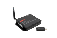
All WSDA® base stations and gateways |
|
Compatible sensors |
Type J, K, N, R, S, T, E and B thermocouples |
|
Connectors |
Type-1 standard mini (SM) connectors for flat pin thermocouples |
|
Software |
SensorCloud™, SensorConnect™, Node Commander®, Windows 7 (or newer) |
|
Software development |
Open-source MicroStrain Communications Library (MSCL) with sample code available in C++,Python,and.NET formats (OS and computing platform independent): http://lord-microstrain.github.io/MSCL/ |
|
Regulatory compliance |
FCC (U.S.), IC (Canada), ROHS |
General Documentation
Mechanical Prints (Uncontrolled)
What is Multipath?
Multipath is the phenomenon whereby a radio signal arrives at a receiver’s antenna by more than one path. This occurs by the reflection, diffraction, or scattering of radio waves from atmospheric ducting, reflection from water bodies or terrestrial objects (like mountains), etc.
Does Multipath impact signal strength?
Yes, multipath propagation of radio signals causes fading of the transmitted signal, which can be indicated by fluctuations in signal strength when received by the signal receiver.
How do I mitigate Multipath?
Pe-position base station or node to mitigate possible multipath interference.
Ensure a clear path to the antenna for the strongest signal, enhancing the strength of the strongest signal AND reducing the strength of the weaker signals.
Learn More: Mutipath Propagation
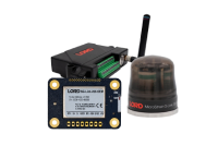
The WSDA-RGD (with internal GX3 inertial sensor) is configured to produce the following messages on startup.
GPS Data (1 Hz):
AHRS Data (100 Hz):
From this output the WSDA logs:
GPS (1 Hz):
AHRS (100 Hz):
The WSDA-RGD does not log any data until it gets a valid time, if it is set to get time from GPS only it will not log any output from the GX3 until the UTC timestamp from the GX3 is valid, even though the GX3 is producing valid AHRS data.
This data is not user configurable and is not available as a live stream through LiveConnect.
All LORD MicroStrain wireless sensor nodes, wireless base stations, and wireless sensor data aggregators are shipped from the factory with their radio frequency set to channel 15 (2.425 GHz).
This channel setting was established during 2012.
Previously all wireless products were set to channel 25 (2.475 GHz).
If you are mixing new nodes and base stations with older nodes and base stations, please be cognizant of these different channel settings.
The Node Discovery function of Node Commander will help you sort out which nodes are on what channels; Node Discovery is channel independent and allows the base station to communicate with any node, no matter what channel it is on
Sampling methods such as synchronized sampling, low duty cycle, network broadcast, etc. require that all nodes are on the same frequency so you will want to insure that you have adjusted the channels settings of the nodes to suit.
The wireless nodes all have 2 Mbytes of datalogging memory. This 2 Mbytes is organized into 8,191 ‘pages’ of memory, each page holds 132 data points. The maximum number of data points that can be held in memory can be calculated as follows: 8,191 pages x 132 data points/page = 1,081,212 total data points.
Now the question arises, ‘how long can a node datalog before its memory is full?’. The answer is that it varies depending on how many channels are being sampled and what sampling rate has been set. Here are two examples:
Let’s set a V-Link-LXRS so that channel 1 is active with a datalogging sampling rate of 2048 samples per second and we launch continuous datalogging. Our calculation would be:
Let’s set a G-Link-LXRS so that channels 1, 2 and 3 are active with a datalogging sampling rate of 32 samples per second and we launch continuous datalogging. Our calculation would be:
In FINITE sampling, the user sets a total number of samples to be taken which equates to a time period. Because the sampling rate per second is known, the user can adjust the number of samples to be taken to determine how long the sampling period will be.
In CONTINUOUS sampling, the user does not set the total number of samples and therefore does not set the time of the sampling period. By selecting CONTINUOUS sampling, the user is instructing the system to sample data until the user manually stops the sampling (via software), the power is cycled, the on-board datalogging memory is full, the battery dies, the power fails, etc.
© HBK, Inc 2023
Privacy Statement |
SensorCloud™ Services Agreement |
Terms & Conditions of Sale