

FAQs
Videos
Non-contact LVDTS must be mounted in a non-conductive material, such as those listed below. In special cases NC-LVDTs can be mounted in conductive fixturing, but LORD must perform the calibration with the sensor installed in the fixturing. The calibration repeatability is also contingent on careful axial alignment of the sensor within the fixture.
Acceptable non-contact LVDT fixture materials:
- All polymers
- Carbon fiber (limited information)
- Composites
- Ceramic/Glass
- Wood
Keep in mind that the target material of the NC-DVRT must be a conductive material.
As always, LORD support engineers are available to go over your particular application and work with you to find the optimal way to mount our sensors.
LORD Displacement sensors are offered in smooth and threaded shell versions. Depending on the application, one of these types may make more sense than the other.
Off the shelf, sensors will come with a smooth stainless steel body. For non-gauging contact-type sensors this shell is a 300 series stainless. For gauging contact-types this shell is 400 series.
A smooth shell sensor can be mounted in a fixture or product in a number of ways:
Epoxy the sensor in a close-tolerance through hole
| Pros | Cons |
|---|---|
| Fast integration of the sensor | Core is peramently fixed |
| Provides rigid mounting | Future recalibration difficult or impossible |
| Potential thermal expansion effects |
Use a 3rd party collar clamp to fix the sensor to a product
| Pros | Cons |
|---|---|
| Available in stainless steel and other materials | Requires a means of attaching the collar clamp to the product (Epoxy/fasteners) |
| Offered in a wide range of sizes | Precise sensor alignment is more difficult |
| Sensor is removable |
Through hole with a set screw
| Pros | Cons |
|---|---|
| Fast integration of the sensor | Requires a tapped hole intersecting the sensor hole |
| Stiff mounting, yet removable | Overtightening set screw could damage sensor |
| Resilient to thermal expansion |
Feedthrough/Grommet
| Pros | Cons |
|---|---|
| Sensor is removable | Polymer seals can compromise precise measurements if too soft |
| Grommets can seal around the smooth shell | Threading/accommodation of a grommet |
| Fast integration |
Threaded Shells
Threaded shells are perhaps the easiest to install. They require a tapped hole of the mating thread (shells are offered in both Metric and imperial), and either a follower nut or a set screw to fix the sensor into position. The threaded body allows for precise axial positioning of the sensor, the ability to remove the sensor in the future, and an increased magnetic shielding from the surroundings.
Mounting Rules of Thumb
Avoid Magnetic Influences
All LORD LVDT Sensors are susceptible to outside magnet fields (both static or dynamic). Non-gauging type sensors with smooth shells are the most susceptible due to the thin walls of the 300 series shell. Gauging type sensors, NC-LVDTS, and threaded shell versions of all models have higher resistance to external fields, but it is still recommended that sensors not be exposed to any magnetic fields during use. External fields will influence the output of the sensor and result in incorrect readings. If magnet fields are unavoidable, contact a LORD support engineer to discuss options for custom calibrations or magnetic shielding.
Appropriate Fixture Materials
As a general rule, fixturing should be non-magnetic for all sensors. For NC-LVDTs there is an additional requirement is that the fixture is non-conductive (the target of the NC-LVDT should, however, be conductive!). Depending on the sensor type, and performance customizations (high-res, low noise, low drift, etc.) Magnetic materials, and even "mostly" non-magnetic materials, can have an effect on sensor output. In cases where sensors are mounted in non-ideal materials, LORD can calibrate the sensor in your fixturing to remove any offset or gain errors the fixture is contributing, bringing the sensor back into peak performance.
Sensors with threaded shells, LS-LVDTs, and gauging-type sensors have higher resistance to nearby magnetic materials than the free-sliding smooth body sensors (M-, and S-LVDTs).
Examples of acceptable fixturing materials for Contact-type sensors:
- All polymers/plastics
- Carbon Fiber/composites
- Aluminum
- Non-magnetic stainless steel (300 series)
- Wood
- Ceramic
- Titanium
- Other non-magnetic metals
Examples of influential materials:
- 400-series stainless
- Ferrite
- Iron
- Carbon Steels
Non-contact LVDTS must be mounted in a non-conductive material, such as those listed below. In special cases NC-LVDTs can be mounted in conductive fixturing, but LORD must perform the calibration with the sensor installed in the fixturing. The calibration repeatability is also contingent on careful axial alignment of the sensor within the fixture.
Acceptable Non-contact LVDT fixture materials:
- All Polymers
- Carbon Fiber (limited information)
- Composits
- Wood
- Ceramic
As always, LORD support engineers are available to go over your particular application and work with you to find the optimal way to mount our sensors.
Plan for cable strain relief
Plan to have some room at the back of the sensor for routing the cable out and away to the signal conditioner. The cable we use in our sensor is armored, but is not unbreakable. Pulling on the cable at a sharp angle against the back of the sensor is likely to cause a cable failure, either at the epoxy edge or internal to the sensor. Use your thumb- if the cable turns tighter than the diameter of you thumb, it may be too tight.
Avoid twisting the sensor independent of the cable
It sounds easy to avoid, but we have seen it many times. When installing a threaded body sensor, be sure that the cable is spinning with the sensor! If the cable it plugged into the signal conditioner, or not freely rotating as the sensor is inserted it will eventually over-twist and snap.
Similar to the sensor shells, cores for non-gauging sensors are offered in both smooth and threaded versions.
Cores for Micro and Submini sensors ship without threads unless otherwise specified on the order. Long-Stroke sensors ship with a threaded tip and two flange nuts, unless otherwise specified.
Smooth cores can be mounted in a couple of ways:
Epoxy the core in a close-tolerance through hole
| Pros | Cons |
|---|---|
| Fast integration | Core is peramently fixed |
| Provides rigid mounting | Future removal difficult or impossible |
| Potential thermal expansion effects |
Through hole with set screw
| Pros | Cons |
|---|---|
| Fast integration | Requires a tapped hole intersecting the core hole |
| Stiff mounting, yet removable | Over-tightening set screw could damage core |
| Resilient to thermal expansion |
Feedthrough/Grommet
| Pros | Cons |
|---|---|
| Core is removable | Polymer seals can compromise precise measurements if too soft |
| Grommets can seal around the core | Threading/accommodation of a grommet |
| Fast integration |
Thread-tipped cores can simply be threaded into the mating tapped hole and held in place with either a follower nut or a set screw.
If your application requires custom mounting, contact a LORD support engineer. Our teams specialize in custom mounting designs to make sensor integration easy.
What is Multipath?
Multipath is the phenomenon whereby a radio signal arrives at a receiver’s antenna by more than one path. This occurs by the reflection, diffraction, or scattering of radio waves from atmospheric ducting, reflection from water bodies or terrestrial objects (like mountains), etc.
Does Multipath impact signal strength?
Yes, multipath propagation of radio signals causes fading of the transmitted signal, which can be indicated by fluctuations in signal strength when received by the signal receiver.
How do I mitigate Multipath?
Pe-position base station or node to mitigate possible multipath interference.
Ensure a clear path to the antenna for the strongest signal, enhancing the strength of the strongest signal AND reducing the strength of the weaker signals.
Learn More: Mutipath Propagation
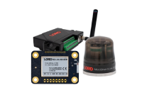
Magnetic fields will not have any impact on the performance of the G-Link-200. In fact, one of the options provided with the G-Link-200 is a 95lb pull strength magnet that gets mounted to the base of the node.
The Low Battery Indicator is a diagnostic channel that indicates the battery level of the node. It is represented by 3 possible values: 0, 1, and 2.
The “0” value indicates that the battery level is good.
The “1” value indicates that the battery level is low. At this level it is recommended that the batteries be replaced. This indicates that critical battery level is imminent. Please replace batteries when this warning indicator is thrown. Once critical battery level indicator is reached the node will stop sampling.
The “2” value indicates that the battery level is critically low. At this level the node will stop sampling.
The expected battery lifetime depends on a combination of variables, such as the sampling mode, sample rate, RF transmit power, number of active channels, etc. To determine the expected battery life of your node please use the Battery Lifetime link provided on the specific node’s product page on our website.
SensorConnect has to be used our 200 series products, found here. There are many how-to videos to help user's get up and running, found here.
The Terms and Conditions of Sale for this inertial sensor can be found here.
To enable customers to try our products risk free, LORD Sensing MicroStrain offers a 30-day return on the purchase of a starter kit. In order to take advantage of this offer, a purchase order or payment for the starter kit is required when the order is placed. If the product is not suited to the application, the product may be returned within 30 days from the date of receipt for a full refund (excluding shipping and handling), as long as the product is unaltered or undamaged. Items can only be returned after LORD Sensing MicroStrain has issued an RMA. Items must be packed to withstand shipping and returned freight pre-paid. LORD Sensing MicroStrain will inspect the items returned and issue a refund or credit once the items have been examined and are deemed to be unaltered or undamaged. Non-standard or custom products may only be returned with LORD Sensing MicroStrain's approval and a re-stocking penalty may be assessed. A 30-Day Return must be initiated by receiving an RMA (Returned Merchandise Authorization from LORD Sensing MicroStrain.
LORD Sensing MicroStrain warrants this product to be free from defective material and workmanship for a period of one (1) year from the original date of purchase. LORD Sensing MicroStrain agrees to repair or replace, at its sole discretion, a defective product if returned to LORD Sensing MicroStrain within the warranty period and accompanied by proof of purchase. This warranty does not extend to any LORD Sensing MicroStrain products which have been subject to misuse, alteration, neglect, accident, incorrect wiring, mis-programming or to use in violation of operating instructions furnished by us, nor extend to any units altered or repaired for warranty defect by anyone other than LORD Sensing MicroStrain. This warranty does not cover any incidental or consequential damages and is in lieu of all other warranties expressed or implied and no representative or person is authorized to assume for us any other liability in connection with the sale of our products. Some states do not allow limitations on how long an implied warranty lasts, and/or the exclusion or limitation of incidental or consequential damages so the above limitations and exclusions may not apply to the original customer.