

Contact for pricing and lead time--a minimum order quantity may apply
Contact for pricing and lead time--a minimum order quantity may apply
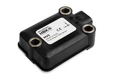
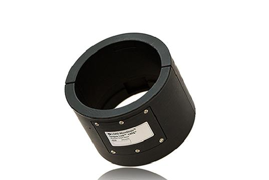
The Torque-Link-LXRS® is a specialized analog sensor node designed to fit over rotating shafts for wireless strain and torque measurements.
Product Highlights
- One or two differential analog input channels designed for full-bridge strain gauge integration
- Ideal for static and dynamic torque measurements with full temperature compensation and bending cancellation
- Rugged ABS housing designed for remote, long-term installation on cylindrical shafts
- Wireless data transmission allows installation on rotating components without a slip ring
- Standard and custom diameters available
- User-programmable sample rates up to 4096 Hz
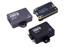
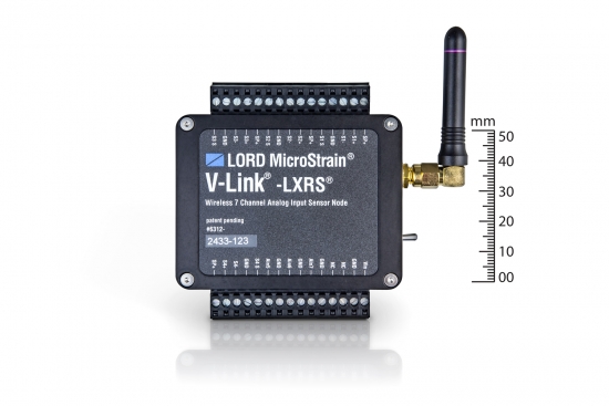
The V-Link® -LXRS® is a versatile seven channel analog wireless sensor node with high sample rates and datalogging capability.
Product Highlights
- Four differential and three single-ended analog input channels and an internal temperature sensor
- Ideal for remote and long term measurement of many Wheatstone bridge and analog-type sensors including: strain, force, torque, pressure, acceleration, vibration, magnetic field, displacement and geophones
- Supports continuous, burst, and event-triggered sampling and datalogging to internal memory
- l User-programmable sample rates up to 10 KHz
- l IP65/66 environmental enclosures available
Wireless Simplicity, Hardwired Reliability
High Performance
- Lossless data throughput and sensor-to-sensor sampling synchronization of ±32 μS in LXRS-enabled modes
Ease of Use
- Wireless framework reduces installation complexity
- Installs over existing strain elements and shafts with no mechanical modifications
- Configurable housing geometry will accommodate any shaft size
- Low power consumption allows extended use
- Remotely configure sensors, acquire, and view sensor data with Node Commander®
Wireless Simplicity, Hardwired Reliability
High Performance
- Node-to-node synchronization up to ±32 microseconds
- High resolution data with 16-bit A/D converter
- Scalable, long range wireless sensor networks up to 2 km
- Lossless data throughput under most operating conditions
Ease of Use
- Rapid deployment with wireless framework
- Event driven triggers for efficient monitoring
- Remotely configure nodes, acquire and view sensor data with Node Commander®.
- Optional web-based SensorCloud™ interface optimizes data storage, viewing, and analysis.
- Easy integration via comprehensive SDK
Cost Effective
- Reduction of costs associated with wiring
- Low-cost per channel with 7 input channels per node
| General | |
|---|---|
|
Sensor input channels |
Differential analog, 1 channel (standard), 2 channels (optional) |
|
Integrated sensors |
Internal temperature, 1 channel |
|
Data storage capacity |
2 M bytes (up to data points) |
| Analog Input Channels | |
|
Measurement range |
Differential: full-bridge, ≥ 350 Ω |
|
Accuracy |
± 0.1% full scale typical |
|
Anti-aliasing filter bandwidth |
Single-pole Butterworth -3 dB cutoff @ 500 Hz |
|
Bridge excitation voltage |
+ 3 V dc (pulsed @ sample rates ≤ 16 Hz to conserve power) |
|
Measurement gain and offset |
User-selectable in software on differential channels, gain values from 20 to 2560 |
| Integrated Temperature Channel | |
|
Measurement range |
-40 °C to 85 °C, ± 2 °C (at 25 °C) typical |
|
Resolution |
12 bit |
| Sampling | |
|
Sampling modes |
Synchronized, low duty cycle, datalogging |
|
Sampling rates |
Continuous sampling: 1 sample/hour to 512 Hz Periodic burst sampling: 32 Hz to 4096 Hz Datalogging: 32 Hz to 4096 Hz |
|
Sample rate stability |
±3 ppm |
|
Network capacity |
Up to 2000 nodes per RF channel (and per gateway) depending on the number of active channels and sampling settings. Refer to the system bandwidth calculator: http://www.microstrain.com/configure-your-system |
|
Synchronization between nodes |
± 32 μsec |
| Operating Parameters | |
|
Wireless communication range |
100 m (typical) |
|
Radio frequency (RF) transceiver carrier |
2.405 to 2.470 GHz direct sequence spread spectrum over 14 channels, license free worldwide, radiated power programmable from 0 dBm (1 mW) to 16 dBm (39 mW); low power option available for use outside the U.S.- limited to 10dBm (10mW) |
|
RF communication protocol |
IEEE 802.15.4 |
|
Power source |
Replaceable, non-rechargable battery pack (3.0 V dc, 1.2 Ah Li/MnO2 batteries in series configuration) |
|
Power consumption |
1 to 25 mA (configuration dependent) |
|
Operating temperature |
-20 ˚C to + 80 ˚C |
|
Angular acceleration limit |
500 g standard (high g option available) |
|
Maximum RPM |
2500 to 4200 RPM (diameter dependent, high RPM option available) |
| Physical Specifications | |
|
Dimensions |
Height 88.9 mm (3.5 inches), ID varies for use on 50.8 to 152.4 mm (2 to 6 inch) diameter shafts (custom sizes available) |
|
Weight |
200 to 525 grams (0.44 to 1.16 lb), depending on size |
|
Environmental rating |
IP66, tested to DO-160 standards for temperature variation, humidity, and vibration |
|
Enclosure material |
ABS thermoplastic |
| Integration | |
|
Compatible gateways |
All WSDA® base stations and gateways |
|
Compatible sensors |
Bridge type analog sensors |
|
Connectors |
Strain gauge and battery interface connectors |
|
Shunt calibration |
Internal shunt calibration resistor 499 KΩ |
|
Software |
SensorCloud™, Node Commander®, Windows 7 (or newer) |
|
Software development |
Open-source MicroStrain Communications Library (MSCL) with sample code available in C++,Python,and.NET formats (OS and computing platform independent): http://lord-microstrain.github.io/MSCL/ |
|
Regulatory compliance |
FCC (U.S.), IC (Canada), ROHS |
| General | |
|---|---|
|
Sensor input channels |
Differential analog, 4 channels Single-ended analog, 3 channels |
|
Integrated sensors |
Internal temperature, 1 channel |
|
Data storage capacity |
4 M bytes (up to 2,000,000 data points, data type dependent) |
| Analog Input Channels | |
|
Measurement range |
Differential: full-bridge, ≥ 350 Ω (factory configurable) Single-ended: 0 to 3 V dc |
|
Accuracy |
± 0.1% full scale typical |
|
Resolution |
16 bit |
|
Anti-aliasing filter bandwidth |
Single-pole Butterworth -3 dB cutoff @ 250 Hz (factory configurable) |
|
Bridge excitation voltage |
+3 V dc, 50 mA total for all channels (pulsed @ sample rates ≤ 16 Hz to conserve power) |
|
Measurement gain and offset |
User-selectable in software on differential channels gain values from 21 to 13074 |
| Integrated Temperature Channel | |
|
Measurement range |
-40 °C to 85 °C |
|
Accuracy |
± 2 °C (at 25 °C) typical |
|
Resolution |
16 bit |
| Sampling | |
|
Sampling modes |
Synchronized, low duty cycle, datalogging, event-triggered |
|
Sampling rates |
Continuous sampling: 1 sample/hour to 512 Hz Periodic burst sampling: 32 Hz to 10 KHz Datalogging: 32 Hz to 10 KHz |
|
Sample rate stability |
± 3 ppm |
|
Network capacity |
Up to 2000 nodes per RF channel (and per gateway) depending on the number of active channels and sampling settings. Refer to the system bandwidth calculator: http://www.microstrain.com/configure-your-system |
|
Synchronization between nodes |
± 32 μsec |
| Operating Parameters | |
|
Radio frequency (RF) transceiver carrier |
2.405 to 2.470 GHz direct sequence spread spectrum over 14 channels, license free worldwide, radiated power programmable from 0 dBm (1 mW) to 16 dBm (39 mW); low power option available for use outside the U.S.- limited to 10dBm (10mW) |
|
Range for bi-directional RF link |
Outdoor/line-of-sight: 2 km (ideal) *, 800 m (typical)** Indoor/obstructions: 50 m (typical)** |
|
RF communication protocol |
IEEE 802.15.4 |
|
Power source |
Internal: 3.7 V dc, 650 mAh lithium ion rechargeable battery External: +3.2 to +9.0 V dc |
|
Power consumption |
See power profile : |
|
Operating temperature |
-20 ˚C to + 60 ˚C (extended temperature range available with custom battery/enclosure, -40 ˚C to + 85 ˚C electronics only) |
|
Acceleration limit |
500 g standard (high g option available) |
| Physical Specifications | |
|
Dimensions |
74 mm x 79 mm x 21 mm |
|
Weight |
141 grams |
|
Environmental rating |
Indoor use (IP65/66 enclosures available) |
|
Enclosure material |
Anodized aluminum |
| Integration | |
|
Compatible gateways |
All WSDA® base stations and gateways |
|
Compatible sensors |
Bridge type analog sensors, 0 to 3 V dc analog sensors |
|
Connectors |
Screw terminal block |
|
Shunt calibration |
Internal shunt calibration resistor 499 KΩ, differential channels |
|
Software |
SensorCloud™, Node Commander®, Windows XP/Vista/7 |
|
Software development |
Open-source MicroStrain Communications Library (MSCL) with sample code available in C++,Python,and.NET formats (OS and computing platform independent): http://lord-microstrain.github.io/MSCL/ |
|
Regulatory compliance |
FCC (U.S.), IC (Canada), CE, ROHS |
*Measured with antennas elevated, no obstructions, and no RF interferers.
**Actual range varies depending on conditions such as obstructions, RF interference, antenna height, & antenna orientation.
General Documentation
- Torque-Link-LXRS Datasheet
- Torque-Link-LXRS Quick Start Guide
- Torque-Link-LXRS User Manual
- Node Commander Wireless Sensing Software User Manual
- Wireless Products Comparison
Videos
General Documentation
- V-Link®-LXRS® Product Manual
- V-Link®-LXRS® Product Datasheet
- V-Link®–LXRS® Quick Start Guide
- V-Link®-LXRS® Document of Conformity
- Node Commander Wireless Sensing Software User Manual
- Wireless Products Comparison
Technical Notes
- Powering a Wireless Node with Sources Greater Than 9 Volts
- High Cycle Vibration and Function Test
- Event Driven Sampling
- Measuring Voltages Above 3 Volts with V-Link®-LXRS®
- LXRS® Firmware Upgrades
- Using a 4 to 20 mA Pressure Transducer
- Control a Relay with a Wireless Node
- Measuring Small Current
- Measuring Small Voltages
- Outputting a 4 to 20 mA Current Loop
- Using Pressure Transducers
- Battery Use and Replacement
- V-Link®-LXRS® 350 Ohm Tester Board
- V-Link®-LXRS® 1000 Ohm Tester Board
- V-Link®-LXRS® Pin Assignments
- Using the 50g, 100g, 200g or 500g Triaxial Accelerometer Cube
- IP and NEMA Rated Enclosures for Wireless Nodes
- Calculating a Linear Slope with Microsoft Excel®
- Using a Load Cell with V-Link®-LXRS™ and SG-Link®-LXRS®
- V-Link®-LXRS® Power Profile
- Wireless Sensor Node Power Profiles
- Using External Power With Wireless Sensor Nodes
- Using the DEMOD-DC® with V-Link®-LXRS® and SG-Link®-LXRS®
- Synchronized Sampling on Startup
- Distance Measurement with an IR Sensor
- Using Differential Inputs for a RTD
Mechanical Drawings (Uncontrolled)
- V-Link®–LXRS® Dimensional Drawing
- 6313-3100 V-Link-IP66-XL-ENCL
- 6313-3100 IP66/NEMA4X Enclosure for V-Link®-LXRS® (2 batteries)
Videos