Product no longer stocked – limited availability
Contact for pricing and lead time--a minimum order quantity may apply

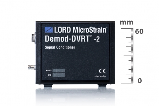
Designed for ease of use and general versatility, this printed circuit card provides complete temperature compensated conditioning for any sensors. The DEMOD-DVRT® -TC utilizes both alternating current and direct current excitation of the sensor’s inductive bridge to accurately measure position in the face of temperature gradients. Each card contains the requisite components to facilitate plug-and-play use, including active, jumper selectable low pass filters, input supply line filters with reverse input protection, and output line buffers. The DEMOD-DVRT® -TC sine wave excitation and synchronous demodulator provide excellent noise rejection and elimination of thermally induced potentials.

Datasheet
Where to Buy?
U.S. International OEM

High Performance

  • Temperature compensated signal conditioning
  • Precision synchronous demodulation
  • Rapid warm-up time

Ease of Use

  • Plug-and-play with LORD MicroStrain® motherboards
  • Compatible with all LORD MicroStrain® DVRT sensors
  • Adjustable trimmers to set resolution range

Compensates for a temperature gradient across the sensor

Sensor types

inductive (DVRT®)

Excitation

regulated sinewave, 70 KHz typical

Demodulation

synchronous, DC output

Output

± 4.5 volts typical

Gain

factory adjustable 10-10,000

Low pass filter

2 pole, active Butterworth, 3 dB down @ 1 KHz standard; factory adjustable 10 Hz-8 Khz

Supply voltage

motherboard supplies power (typical), ± 6.5 volts min, ± 16 volts max (when used without motherboard)

Supply current

30 milliamps per rail

Warm-up time

15 minutes recommended

Operating temperature

-40 to 85˚C

PC board size

120mm x 48mm x 20mm (thick)

Connectors

10 pin, .1" pitch header (power, ground); LEMO 4 pin receptacle (bridge points); BNC (analog output)

Trimmers

offset (std.)


There are no downloads for this product.

The DEMOD-DVRT and the DEMOD-DVRT-TC signal conditioners both have a Low Pass Filter.

http://www.microstrain.com/displacement/demod-dvrt

http://www.microstrain.com/displacement/demod-dvrt-tc

The filter is described as: 2 pole, active Butterworth, 3 dB down @ 800 Hz standard; factory adjustable 10 Hz-8 Khz

The filter is modified by manipulating resistors on the circuit board.

Resistors may either be removed or added or both.

These resistors may go into standoff sockets or require soldering/desoldering on the circuit board surface.

After the rework is done, good practice dictates that the signal conditioner and its paired sensor be recalibrated to reflect changes in noise characteristics.

We recommend that such work be done here at the factory.


As an example. here is the Quick Start Guide for the M-DVRT-9: http://files.microstrain.com/Micro_Sub_DVRT_Quick_Start_Guide.pdf

Page 7 refers to the Slope and Offset that you will need to enter into the Smart Motherboard software.

In the Smart Motherboard software, click Tools.

Click Configuration and the Configuration screen appears.

Select the appropriate channel (remember that each channel, i.e., each DVRT and DEMOD –DVRT signal conditioner card in the Smart Motherboard is calibrated separately) by checking the Channel check box.

Select the Linear Radio Button.

Enter the Slope and Offset in the number scroll boxes.

Select None in the Peak Detect drop-down.

Change the Units from Volts to mm (for millimeters) by wiping through with your mouse.

Click File.

Click Save As Default.

Click File.

Click Return and you are ready to sample in millimeters.

A run-time component named ' tabctl32.ocx' has not been automatically registered with your Windows system for some reason.

Let’s register it manually:

Download the component http://download.microstrain.com.s3.amazonaws.com/component.zip.

Unzip the file.

Copy the component into the following folder on your computer: C:\WINDOWS\system32.

Click the Windows Start.

Click Run.

The Run window will appear.

Cut and paste (or type) this command into the Open drop-down box: regsvr32 c:\windows\system32\tabctl32.ocx

Click OK and you will receive a confirming message that the component has been registered.

Click OK in the message box.

Now try your Smart Motherboard application and the error will have been cured.


If you are using the standard cable type supplied with the DVRT sensors, 20 feet is the maximum for M-DVRT and MG-DVRT, and 60 feet is the maximum for S-DVRT, SG-DVRT and NC-DVRT. If you require longer cable lengths, LORD MicroStrain® can provide custom cables of lower resistance.

No, carbon fiber has not been shown to pose a problem.

In most cases, MicroStrain calibrates every DVRT with its accompanying electronics and provides a detailed calibration certificate. The certificate provides 3 methods of calibration and all the particulars including formulas to resolve voltage into engineering units.

  • Standard Least Squares Linear Fit provides a simple mathematical method to convert sensor output to displacement and delivers reasonable accuracy.
  • Polynomial Fit provides a more mathematically intensive method to convert sensor output to displacement and in turn delivers a high degree of accuracy. A possible drawback to some users of this method may be that it can not accurately report measurements beyond its stroke length (i.e., over-stroking).
  • Multi-Segment Linear Fit provides the most mathematically intensive method to convert sensor output to displacement, delivers a high degree of accuracy and is not subject to the drawback of over-stroking.

The output is an analog DC voltage proportional to linear displacement.  The full scale voltage is optionally +/-5 volts or 0-10 volts.  The analog voltage is easily read using a multi-meter or DAQ.  The voltage can also be read in the digital domain by using LORD MicroStrain® Smart Motherboards.  These Smart Motherboards provide a data gateway to PC-based software or to user-programmable LCD displays on the motherboard itself.

Typically, every DVRT is calibrated at the factory with its accompanying DEMOD signal conditioner.  The calibration is made over the entire system (DVRT and DEMOD) to insure the highest accuracy.  DVRTs and DEMODS are color-coded to insure that they stay together as a pair when in use.

No.  LORD MicroStrain® makes a DEMOD-DC which provides an alternate method of DVRT signal conditioning.  The DEMOD-DC provides conditioning as an in-line connector and connects to your DAQ.  Although not normally recommended, a DEMOD-DVRT or a DEMOD-DVRT-TC can be used without its Motherboard enclosure; external power is the only requirement.

The term ‘Motherboard’ refers to the LORD MicroStrain® DEMOD-DVRT or DEMOD-DVRT-TC signal conditioner mounting chassis.  The standard Motherboard provides a mounting slot and power to the individual DEMODs.  The Smart Motherboard provides a mounting slot, power and digital communications (RS-232) to the individual DEMODs.  Both Motherboard and Smart Motherboard provide analog ouput to a DAQ.  In addition, Smart Motherboard provides digital output to a computer.  Motherboards and Smart motherboards can accommodate 1 to 8 DEMOD cards.

In a word, no. The design of an LVDT’s coil forms a Wheatstone full bridge and the design of LORD's DVRT coil forms a Wheatstone half-bridge. LORD MicroStrain® signal conditioning electronics are designed for the half-bridge.  Likewise, a DVRT can not use a LVDT's signal conditioning electronics.

Not what you're looking for? Visit our FAQ page or contact our Sales team.

Contact Sales

Please use the form below to contact us or call 802 862 6629.

By submitting your personal information on this form, you give Parker LORD permission to contact you by phone, email or newsletter with more information about our products and services. If you do not wish to be contacted, you may unsubscribe at any time. For further details, please read our Privacy Statement*.
*https://www.parker.com/privacy